How to Draw and Analyse Free Body Diagrams (FBDs)
In this free engineering tutorial we shall review:
- What is a Free Body Diagram (FBD)
- Steps to draw a Free Body Diagram
- Representing supports in Free Body Diagrams
- Examples of Free Body Diagrams
What is a Free Body Diagram (FBD)
A free-body diagram is a sketch of a body, a portion of a body, or two or more bodies completely isolated from all other bodies. It shows the external forces and couples acting on the system (drawn carefully with respect to location, direction and magnitude). The forces may result from externally applied pushes or pulls, from gravity forces such as the bodies own weight, from forces exerted by other bodies and must include reactions from any supports.
The free-body diagram is one of the most important steps in the solution of problems in engineering.
Steps to Draw a FBD
1. Decide which body or combination of bodies is to be isolated.
2. Draw the boundary which isolates the body from all surrounding bodies and supports.
3. Add all known forces as vector arrows showing position and direction and with magnitude (including units) written alongside. Include the weight of the bodies where appreciable. Unknown forces should have the magnitude and direction represented by a symbol. If the sense (i.e. + or – direction) is unknown assume the positive direction. The calculations will give a negative value for the force if wrong.
4. Draw the co-ordinate axes.
5. Put on essential dimensions but do not clutter the diagram with unnecessary information.
Supports for FBDs
Structures that interact with the ground can be modelled with different types of ‘supports’.

In the diagram above, the top row shows the structure and the bottom row shows the FBD.
For the simple joints shown there is a reaction Ry due to the presence of the surface reaction force pushing upwards on the structure – this is the reaction force due to the weight of the structure acting down. Rx is present because we know that if we try to push the structure in the x direction there will be a resistance of some sort.
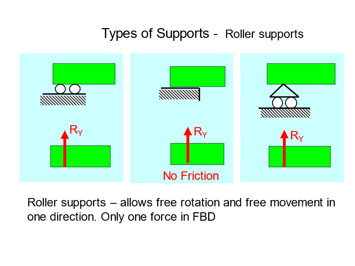
Roller Supports for Free Body Diagrams
In the diagram above, the top row shows the structure and the bottom row shows the FBD.
In each case the structure is either on a roller (frictionless wheel) or in the centre a frictionless table. Correspondingly, there is no resistance in the x-direction, hence there is no need for a reaction force, Rx in this case. Ry is still present to represent the reaction force upwards due to the weight of the structure.

Fixed Supports for Free Body Diagrams
In the diagram above, the top row shows the structure and the bottom row shows the FBD.
This represents a simple beam fixed at one end, often referred to as a cantilever beam. The fixing at the wall prevents any rotation hence the inclusion of a reaction moment, M, to represent the resistance in the rotational sense provided by the wall. The wall prevents the beam from falling down, hence the inclusion of a reaction force, Ry, upwards. The wall prevents the beam moving in the x-direction, hence the inclusion of a reaction force, Rx.
Example Free Body Diagram (FBD) of a Truss

Truss Free Body Diagram
The example shown above shows how we can represent an entire structure (on the left) as a simple FBD (on the right). Note how we have removed the supports from the left and replaced them with corresponding reaction forces on the right in the FBD. We also can omit a lot of the unnecessary detail such as the individual truss members.
Example Free Body Diagram (FBD) of a Cantilever

Cantilever Free Body Diagram
The example shown above show us a representation of a cantilever beam which can be thought of as representing a simple aircraft wing. On the left we can see that the beam is fixed into the wall this could be the aircraft fuselage for instance. We can also see a variety of point loads on the left acting on the wing. On the right-hand side of the diagram we can see the free body diagram representation. Here, fixed support is replaced with the appropriate forces.
Example Free Body Diagram of Person in a Lift
Let us now consider a simple example of a person in a lift as shown below. The lift is supported by a cable shown on the top of the diagram. The combined weight of the lift and the person is represented by W. Weight is a force which always acts downwards towards the centre of the earth. The value of white W can be found from W = mg where m represents the mass and g represents the acceleration due to gravity.

Person in a Lift
The free body diagram for the situation shown above is shown below:
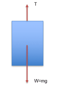
Person in a Lift Free Body Diagram
The free body diagram shown above simplifies they situation and shows that there are just two forces acting on the system. There is a force in the cable whose job it is to hold the lift up and stop it from falling down and we have used the letter T to represent this force which is a tension force. The other force acting on the system is the weight which can be seen to be acting down home diagram.
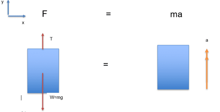
Let us assume that they lift is stationary and therefore the velocity and acceleration are both zero. below we have a diagram which shows the free body diagram on the left and on the right a similar diagram which shows accelerations instead of forces. Note the double arrow to represent acceleration. Now in this example we have stated that the acceleration a is zero, i.e. a=0.
On the left if we take vertically upwards as positive then we can state the forces mathematically as T – W. On the right, we know that a=0. Furthermore, we know from Newtons laws of motion that F=ma.
Newton’s Laws for Person in a Lift Free Body Diagram
If we put all of this together, we can state:

Hence:
T = W = mg
This equation tells us is that the tension force in the cable holding the lift up, T, is equal to the weight of the lift and person combined, W.
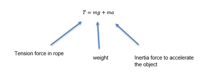
Now let us consider the case of the lift accelerating vertically upwards, with an acceleration a:

Equations for Person in a Lift Free Body Diagram
If we put all of this together, we can state:

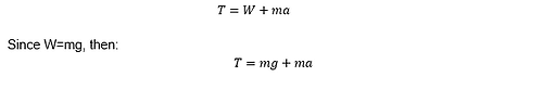
This equation tells us is that the tension force in the cable , T, is equal to the weight of the lift and person combined, W PLUS an additional terms, ma, to represent the inertia force required to accelerate the lift upwards.
Example Free Body Diagram of Truck Pulling a Trailer
A 10tonne truck hauls a 20 tonne trailer. If the truck starts from rest on a level road with a tractive force of 20 kN between the driving wheels and the road determine the tension in the horizontal drawbar and the acceleration of the vehicle.

Equations for Truck and Trailer Free Body Diagram
Online Engineering Courses and Diplomas
If you want to study for an accredited online engineering diploma, check out iLearn Engineering®‘s collection of online engineering courses. All engineering courses and diplomas are available online, with no schedules or deadlines to adhere to and you study at your own pace from the comfort of your home.
Why not check out the online engineering short courses specifically in aerospace engineering:
Diploma in Aerospace Structures
Diploma in Principles of Flight
Diploma in Aerodynamics, Propulsion and Space
Alternatively, you can view all our online engineering courses here.
Recent Posts
Civil Engineering Courses and Diplomas: Topics, Skills and Career Routes
Civil Engineering Courses and Diplomas: Topics, Skills and Career Routes Introduction Civil engineering is the backbone of modern society. From roads and bridges to skyscrapers and water systems, civil engineers design, build, and maintain the infrastructure that keeps the world running. If you’re considering a civil engineering course or diploma, understanding what it covers is […]
What Is a Diploma in Engineering? Courses, Levels and Career Routes Explained
What Is a Diploma in Engineering? Courses, Levels and Career Routes Explained Introduction Engineering shapes the world around us, from the buildings we live in to the technology we use every day. But for many aspiring engineers, the biggest question is not whether to pursue engineering, but how to start. Traditional university degrees are not […]
Engineering Courses: How to Choose the Right Route for Your Career
Engineering Courses: How to Choose the Right Route for Your Career Introduction Choosing an engineering course can feel like standing at the beginning of several different roads, each leading towards a different kind of future. One route may lead into mechanical systems and manufacturing. Another may lead towards aircraft, infrastructure, electronics, computing, renewable energy or […]