How to Calculate Bending Stress
When a beam is subjected to loading acting on a plane passing through the beam’s axis, the beam deforms, or ‘bends’. The beam reacts to the external loads with the internal shear force and bending moments. Bending stress is a fundamental concept in structural engineering and mechanics of materials. It occurs when an external force or moment is applied to a beam, causing it to bend. As a result, different sections of the beam experience compressive and tensile stresses. The maximum bending stress occurs at the outermost fibres of the beam, farthest from the neutral axis. Understanding bending stress is crucial in designing beams and structural elements that can withstand applied loads safely.
Beam Bending Diagram
The diagram below shows typical bending of a simply supported beam (e.g., bridge beams in structures) and a cantilever (e.g., aircraft wings, cantilever beams)

The diagram above shows typical bending of a simply supported beam (e.g. bridge, beams in structures) and a cantilever (e.g. aircraft wings, cantilever beams).
The photograph below shows the internal structure of an Airbus A380 wing undergoing a fatigue test. The photograph shows the wing in a loaded and unloaded condition (during take-off, the wing bends upwards as it takes the weight of the aircraft). You can clearly see the magnitude of this deflection by comparing the wing deformation to the image of the man to the right of the diagram!

By making the following assumptions and applying the knowledge we already have on static equilibrium, stress and strain it is possible to obtain a simple equation for stress in a beam.
Assumptions in Bending Stress Theory
1. The bar is initially straight and of constant cross-section.
2. The material is homogeneous, isotropic and obeys Hooke’s Law.
3. The bar bends in a vertical plane as shown.
4. Plane transverse sections remain plane after bending.
5. Lateral compression between layers of the material is negligible.
6. The radius of curvature of the beam is large compared with the transverse dimensions

The above equation of bending can be used in a number of different ways, depending on which of the 6 parameters we know. However, a typical arrangement is :
Second Moment of Area
The second moment of area is a measure of the stiffness of the shape of the cross-section of the beam.
\[ \ I = ∫ y² dA \]
i.e. the integral of an elemental area multiplied by a distance squared – hence the name second moment of area.
Whilst in principle, the cross-section of a beam can have any shape, in practise, the most frequently used beams are manufactured with a cross-section which is rectangular, circular or a combination of rectangles.
Therefore, we can use the following formulae to determine, I, depending on the cross-section:


Example 1
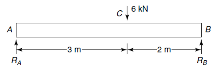
If we now return to a bending problem we have worked on previously you will recall we have found the shear force and bending moment distributions along the beam as shown below
The equation for bending is:
\[ \sigma = \frac{M y}{I}\]
We are mainly concerned with the maximum stress in the beam, and from the above equation it can be seen that the maximum stress will occur for maximum y and maximum M.
‘y’ is the distance from the neutral axis (centre of beam for symmetrical sections) and so the maximum value of y will occur at the outermost fibres of the material, i.e.
\[ \hat{y} = \frac{d}{2} \]
where ŷ is the maximum value of y.
The maximum value of the bending moment (M) is found from examining our bending moment distribution diagram that we produced earlier and which is copied below for your convenience and was found to be 7.2 kNm at position C:

Let us assume a rectangular cross-section for the beam as follows:

Beam Dimensions:
- Width (b) = 150 mm = 0.15 m
- Depth (d) = 100 mm = 0.10 m
- Bending Moment (M) = 7.2 kN·m = 7.2 × 10³ N·m
Moment of Inertia (I):
I = (b × d³) / 12
I = (0.15 × 0.10³) / 12
I = 1.25 × 10⁻⁵ m⁴
Maximum Stress (σ):
σ = (M × y) / I
y = d / 2
y = 0.10 / 2
y = 0.05 m
σ = (7.2 × 10³ × 0.05) / (1.25 × 10⁻⁵)
σ = 28.8 MPa
Final Answer: The maximum bending stress is 28.8 MPa.
Example 2
I-Beam Bending Stress Calculation
Given Data:
- Flange width (bf) = 200 mm = 0.2 m
- Flange thickness (tf) = 20 mm = 0.02 m
- Web height (hw) = 300 mm = 0.3 m
- Web thickness (tw) = 10 mm = 0.01 m
- Total height (h) = 340 mm = 0.34 m
- Bending Moment (M) = 50 kN·m = 50 × 10³ N·m
Moment of Inertia (I):
I = (bf – tw) × hw3
I = (0.2 × 0.34³) / 12 – ((0.2 – 0.01) × 0.3³) / 12
I = (0.00786 / 12) – (0.00513 / 12)
I = 2.27 × 10⁻⁴ m⁴
Maximum Stress (σ):
y = h / 2
y = 0.34 / 2 = 0.17 m
σ = (M × y) / I
σ = (50 × 10³ × 0.17) / (2.27 × 10⁻⁴)
σ = 37.4 MPa
Final Answer: The maximum bending stress is 37.4 MPa.
Interested in our engineering courses?
If you are interested in civil or mechanical engineering courses and qualifications, we have a complete range for you to choose from.
Diploma in Mechanical Engineering
Diploma in Mechanical Technology
Diploma in Structural Engineering
Higher International Certificate in Civil Engineering
Higher International Diploma in Civil Engineering
Higher International Diploma in Mechanical Engineering
Higher International Certificate in Mechanical Engineering
Alternatively, you can view all our online engineering courses here.
Recent Posts
Dynamic Effects of Linear Motion
Dynamic Effects of linear Motion Variable Acceleration Depending on Time In Engineering, motion is often analysed through quantities like displacement, velocity, and acceleration. While many introductory problems assume constant acceleration (like free-fall near Earth’s surface), real-world motion is frequently more complex. One important case is when acceleration changes with time, this is known as variable […]
A Quick Guide to Thermal Stress
A Quick Guide to Thermal Stress Thermal expansion and the resulting thermal stress are key concepts in engineering and physics. They describe how materials expand or contract when exposed to temperature changes. Understanding these principles is essential for designing structures and systems that can withstand environmental fluctuations without failure. What is Thermal Expansion? When materials […]
How to Calculate Shear Stress
Introduction to Shear Force and Shear Stress Shear force and shear stress are critical concepts in mechanics and materials science, often encountered in structural engineering and manufacturing. Shear Force refers to the internal force in a material that acts parallel to its cross-section. It is measured in Newtons (N). Shear force arises when two opposing […]