What are the electrical parameters in series and parallel electrical networks?
In our last article, we looked at the principles of operation of electrical cells. In this article we’re going to move on to the electrical parameters in both series and parallel electrical networks.
When we have circuits with more than one resistor, we need to be able to find the effective resistance before we can use Ohm’s law or do any other calculation.
Resistors in Series
The resistors R1, R2 …., Rm in the circuit below are said to be in series because the same current passes through them:
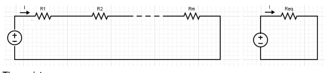
The resistors behave in the same way as the circuit on the right of resistance, where the equivalent resistance can be found by adding the individual resistance.

Since the total resistance is Req. When we use Ohm’s law to find current the equation becomes:
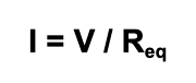
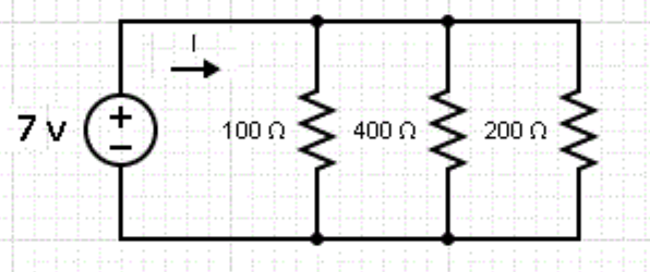
Let’s look at an example. Say we want to find the current, I, passing through, and the voltage across, each of the resistors in this circuit:
The three resistors in series have a resistance Req given by the sum of the three resistances.
Therefore, Req = 100 + 400 + 200 = 700 Ω. The current I passing through R1, R2 and R3 is the same, so we can apply Ohm’s Law I = 7 V / 700 Ω = 0.01 A
The voltage across each resistance is calculated using Ohm’s law for each resistor:
The voltage across 100Ω: VR1 = 100 × I = 100 × 0.01 = 1 V
The voltage across 400Ω: VR2 = 400 × I = 400 × 0.01 = 4 V
The voltage across 200Ω: VR3 = 200 × I = 200 × 0.01 = 2 V
It’s worth noting that the total voltage across each resistor adds up to the voltage supplied by the battery.
Resistors in Parallel
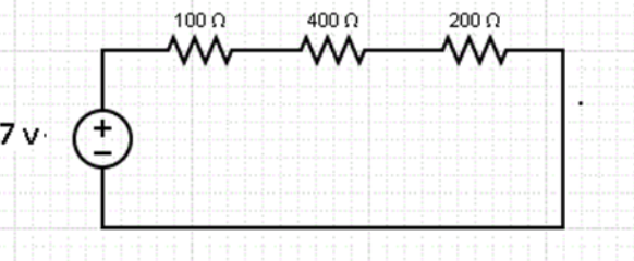
In a parallel circuit, the voltage across each of the resistors R1, R2 …., Rm in the circuit on the left is the same. They behave in the same way as the circuit on the right of resistance Req that is given by the equation:

Combinations of resistors in parallel will ALWAYS have a lower resistance then the smallest resistor present, so can be used to combine high resistors to make an equivalent low resistor:
Let’s have a look at an example. We’re going to find I in the circuit below, as well as the current passing through each of the resistors in the circuit:
The three resistors are in parallel and behave like a resistor with resistance Req given by

Multiply all terms by 400 and simplify to get
400 / Req = 4 + 1 + 2
400 / Reg = 7
Reg = 400/7
Reg = 57.14 Ω
We can now use this to work out the current in the circuit
I = V / R
I = 7 / 57.14
I = 0.1225A
We now use Ohm’s law to find the current passing through each resistor:
The current through the resistor of 100 Ω: I1 = 7 / 100 = 0.07 A
The current through the resistor of 400 Ω: I2 = 7 / 400 = 0.0175A
The current through the resistor of 200 Ω: I3 = 7 / 200 = 0.035A
A real-life example
In real life, circuits often have combinations of both series and parallel resistors. In this case, we need to calculate the equivalent resistor for each combination and may have to use the formulas more than once.
The circuit below contains a combination of series and parallel resistors, and we want to find current I:
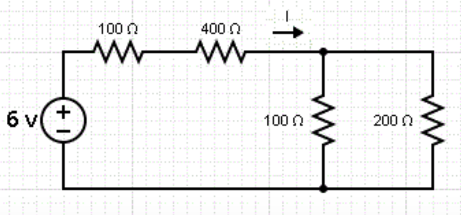
The 100Ω and the 400 Ω resistors are in series, we can combine them and call this Req1
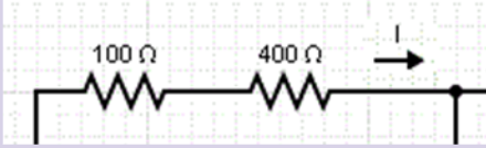
Req1 = 100 + 400 = 500 Ω
The two resistors that are in parallel are grouped as Req2 in the equivalent circuit below and their resistance is given by the equation
1 / Req2 = 1 / 100 + 1 / 200
Req2 = 66.67Ω
So our original circuit can be replaced by
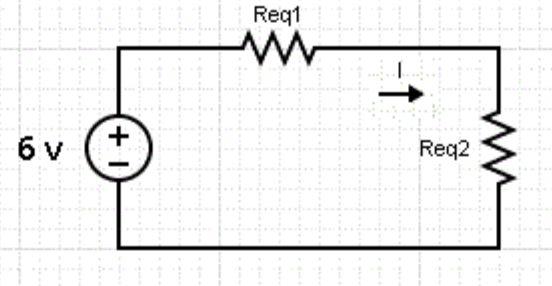
Req1 and Req2 are in series and therefore are equivalent to R given by the sum
R = Req1 + Req2 = 500 + 66.67
R = 566.67Ω
We now use Ohm’s law to find current I.
I = V / R
I= 6 / 566.67
I= 0.0106 A
Keep an eye out for our next articles looking into the principles of operation of a DC electric motor.
Interested in our courses?
You can read more about our selection of accredited online electrical engineering courses here.
Check out individual courses pages below:
Diploma in Electrical and Electronic Engineering
Higher International Certificate in Electrical and Electronic Engineering
Diploma in Electrical Technology
Diploma in Renewable Energy (Electrical)
Higher International Diploma in Electrical and Electronic EngineeringAlternatively, you can view all our online engineering courses here.
Recent Posts
Understanding Key Performance Indicators in Manufacturing
Understanding Key Performance Indicators in Manufacturing Introduction Key Performance Indicators (KPIs), or sometimes written as Key Performance Measures, are some of the key ‘metrics’ that are used to measure the performance of an industrial system. A good KPI for a manufacturing system should be SMART, that is: Specific – It should measure a specific output […]
How Aircraft Structures Evolved: From Fragile Flyers to Engineering Masterpieces
How Aircraft Structures Evolved: From Fragile Flyers to Engineering Masterpieces Introduction As with all other aspects involved with an aircraft, the structural design and layout has changed markedly over the history of flight, in line with technological advances and new discoveries. This section will highlight some of the more substantial developments made during the history […]
Why Lean Manufacturing Matters: Principles of waste
Why Lean Manufacturing Matters: Principles of waste Introduction Lean manufacturing isn’t just a toolkit for improving efficiency, it’s a mindset that reshapes how organisations think about value. At its core, lean focuses on delivering exactly what the customer needs, when they need it, with as little waste as possible. In an increasingly competitive and resource-conscious […]