Understanding different programming techniques
In our previous articles, we looked at PLC systems and what they are, as well as their interface requirements. Now we’re going to look at the different programming techniques we can use in a PLC system.
PLC programming
A PLC program is a set of instructions representing the logic that governs the process the PLC is controlling. There are two main classifications of PLC programming languages. These can be divided into sub-classifications:
- Textual Language
- Instruction list
- Structured text
- Graphical Form
- Ladder Diagrams (LD) (i.e. Ladder Logic)
- Function Block Diagram (FBD)
- Sequential Function Chart (SFC)
While all of these can be used, graphical languages are generally preferable. We’re going to look at some of these languages now.
Ladder Logic
This is the simplest form of PLC programming. It’s also known as ‘relay logic’. The relay contacts used in relay controlled systems are represented using ladder logic. The image below shows a simple example of a ladder diagram:
In this example, two pushbuttons are used to control the same lamp load. When any one of the switches is closed, the lamp will glow. The two horizontal lines are called rungs and the two vertical lines are called rails.
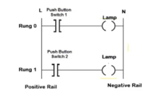
Every rung forms the electrical connectivity between Positive rail (P) and Negative rail (N). This allows the current to flow between input and output devices
Functional Block Diagrams
A Functional Block Diagram (FBD) is a simple graphical method to program multiple functions in a PLC. A function block is a program instruction unit that yields one or more output values when executed.
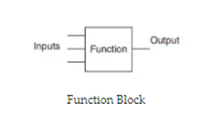
It’s represented as a rectangular block with inputs entering on the left, and outputs leaving on the right. It shows a relationship between the state of the input and output.
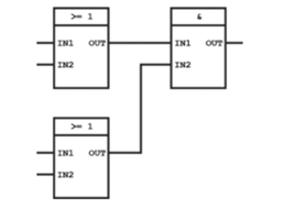
The advantage of using FBD is that any number of inputs and outputs can be used on the functional block. When using multiple input and outputs, you can connect the output of one function block to the input of another.
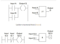
The figure below shows a ladder diagram and its function block equivalent in Siemens notation.
Structured Text Programming
This is a programming language that uses statements to determine what to execute. It follows more conventional programming protocols but it is not case sensitive. A series of statements (logic) consists of expressing assignments and relationships using several operators. The structure’s text operators are listed in the image.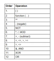
Many early PLCs were not capable of graphical representation of the logic, so it was instead represented as a series of logical expressions in a Boolean format
As programming terminals evolved, it became more common for ladder logic to be used because it was a familiar format used for electro-mechanical control panels. More modern formats, such as state logic and Function Block diagrams, exist, but they are still not as popular as ladder logic. A possible reason for this is that programmers prefer the more visual appeal of ladder logic over structured text programming.
Until approximately the mid-1990s, PLCs were programmed using proprietary programming panels or special-purpose programming terminals, which often had dedicated function keys representing the various logical elements of PLC programs. Some proprietary programming terminals displayed the elements of PLC programs as graphic symbols, but plain ASCII code representations of contacts, coils, and wires were common.
Keep an eye out for our next articles, where we’re going to dive even further into Programmable Logic Controller systems and their uses.
Interested in our courses?
You can read more about our selection of accredited online electrical and electronic engineering courses here.
Check out individual courses pages below:
Diploma in Electrical and Electronic Engineering
Higher International Certificate in Electrical and Electronic Engineering
Diploma in Electrical Technology
Diploma in Renewable Energy (Electrical)
Higher International Diploma in Electrical and Electronic Engineering
Alternatively, you can view all our online engineering courses here.
Recent Posts
Civil Engineering Courses and Diplomas: Topics, Skills and Career Routes
Civil Engineering Courses and Diplomas: Topics, Skills and Career Routes Introduction Civil engineering is the backbone of modern society. From roads and bridges to skyscrapers and water systems, civil engineers design, build, and maintain the infrastructure that keeps the world running. If you’re considering a civil engineering course or diploma, understanding what it covers is […]
What Is a Diploma in Engineering? Courses, Levels and Career Routes Explained
What Is a Diploma in Engineering? Courses, Levels and Career Routes Explained Introduction Engineering shapes the world around us, from the buildings we live in to the technology we use every day. But for many aspiring engineers, the biggest question is not whether to pursue engineering, but how to start. Traditional university degrees are not […]
Engineering Courses: How to Choose the Right Route for Your Career
Engineering Courses: How to Choose the Right Route for Your Career Introduction Choosing an engineering course can feel like standing at the beginning of several different roads, each leading towards a different kind of future. One route may lead into mechanical systems and manufacturing. Another may lead towards aircraft, infrastructure, electronics, computing, renewable energy or […]