How to determine the forces acting in pin-jointed frame structures.
We’re going to continue our series of articles on the calculations used to determine various forces and effects by jumping in to another calculation.
What is a pin joint.
Before looking at the forces acting in a pin joint, we need to know what a pin joint is. A pin joint allows the joined members to swivel, as opposed to a rigid joint that doesn’t. A rigid joint could be welded, whereas a pin joint might be a bolt, rivet, or a swivel pin.
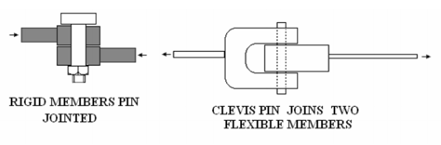
Important points about a pin joint are:
- The connected members are free to rotate.
- The force in the member can only pull or push along the line of the member.
Struts and TIEs
Consider a bar with a pin joint at each end, just like in the diagram below. A pin joint can’t transmit torque from one to another, they can only push or pull on the joint along the direction of its length.
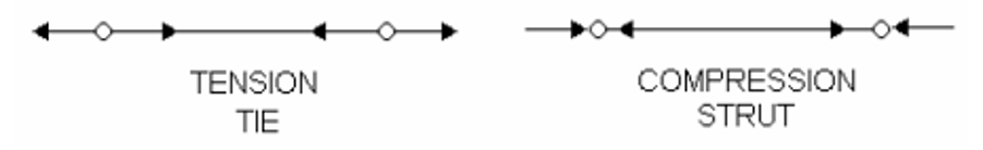
Remember also that the force on the other end of each bar also pushes or pulls and so acts in the opposite direction with equal force. A member in tension is called a TIE and is shown above with arrows pointing inwards at each end. A bar in compression is called a strut and is shown above with arrows pointing outwards at each end.
Let’s check out an example. In the diagram you can see below, the spaces are labelled in between the bars, with the direction of force shown by the arrows.
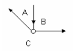
Bar AB is pointing to the joint and is a strut (a compression or push). Bar BC is pointing out of the joint, so it’s a tie (tension or pull). Bar CA is pointing out of the joint and is also a tie. Each bar is always labelled as either a strut or a tie. This video showing examples and notations of struts and ties in force diagrams gives some more information.
Example calculation.
We can check out another example of a force diagram to see if we can calculate the forces. The diagram below shows the truss we’ll examine:
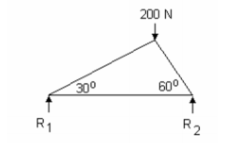
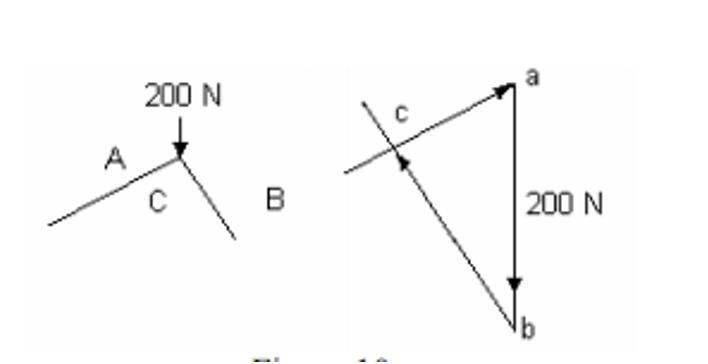
Then we solve the joint with the known force:
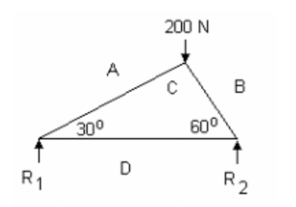
We can use trigonometry to find BC = 200 sin 60 = 173 N (strut) CA = 200 sin 30 = 100 N (strut).
After that we solve the other joint:
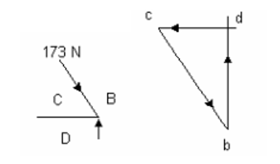
Again, using trigonometry to find BD = R1 = 150 N. CD = 86.5 N (tie). R2 can be easily deduced since the total upward force is 200N then R2 must be 200 – 150 = 50N. The solution for the final joint is:
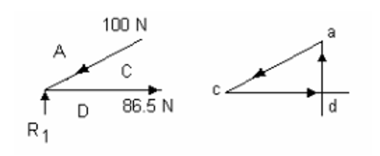
AD = R2 = 50N.
Analytical Approach to Pin-Jointed Truss Structures
The above method described a graphical approach to the solution of pin-jointed truss structures. The alternative approach is to tackle the problem analytically, and one such approach is known as the ‘Method of Joints’.
We’re going to jump into more articles like this one in the future, so make sure you don’t miss out and keep checking our site for more.
Interested in our courses?
Interested in civil or mechanical engineering? Find out more about all the civil engineering courses we have available by clicking here, and the mechanical engineering courses by clicking here.
Diploma in Mechanical Engineering
Diploma in Mechanical Technology
Diploma in Sustainable Construction
Diploma in Structural Engineering
Diploma in Building and Construction Engineering
Higher International Certificate in Civil Engineering
Higher International Diploma in Civil Engineering
Higher International Diploma in Mechanical Engineering
Higher International Certificate in Mechanical Engineering
Alternatively, you can view all our online engineering courses here.
Recent Posts
What Is The Work-Energy Theorem?
What Is The Work-Energy Theorem? The Work-Energy Theorem is a fundamental principle in classical mechanics that connects the concepts of work and kinetic energy. It provides a powerful tool for analysing the motion of objects without relying solely on Newton’s laws in their force-acceleration form. The principle of work and kinetic energy (also known as […]
How Motion in a Circle Affects System Dynamics
How Motion in a Circle Affects System Dynamics In engineering applications, circular motion is encountered in various systems such as rotating machinery, turbines, gears, flywheels, and vehicle dynamics. Unlike linear motion, circular motion involves continuously changing direction, resulting in dynamic effects that must be analysed to ensure safe and efficient design. Understanding these dynamics is […]
How to Analyse Force as a Function of Time
How to Analyse Force as a Function of Time In the previous post ( Dynamic Effects of Linear Motion) we considered the motion of a body (such as a vehicle or component in a machine) moving in a straight line when the acceleration was changing during the motion. We shall now consider the case where […]