How do we analyse the deflection of simply supported beams using calculus.
In our previous article on deflection in simply supported beams, we looked at calculating deflection using standard tables. In this article, however, our focus will be on calculating deflection using calculus.
Relationship Between Deflection, Slope and Radius of Curvature
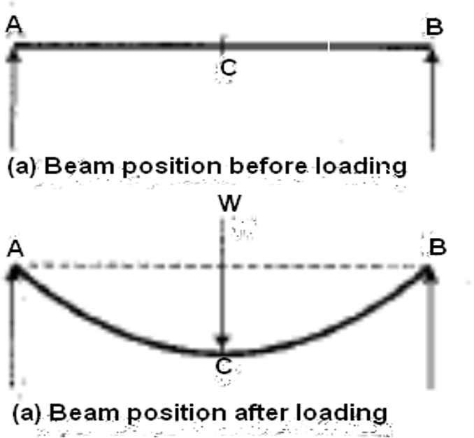
As we mentioned in our previous articles, a beam bends when it’s subject to loading. In the image below, you can see a simple beam before being loaded, then the same beam after being loaded.
To derive an expression relating to the slope, deflection, and radius of curvature of a beam, let us consider a small portion (labelled AB) of a beam bent into an arc, shown the image below:
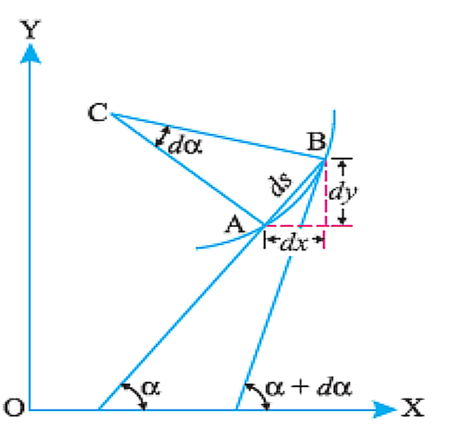
Let ds = Length of beam AB
C= = the center of the arc (into which the beam has been bent),
= Angle which the tangent at A makes with XX – axis, and +d = Angle which the tangent at B makes with XX-axis
We then find, from the geometry of the figure, that:
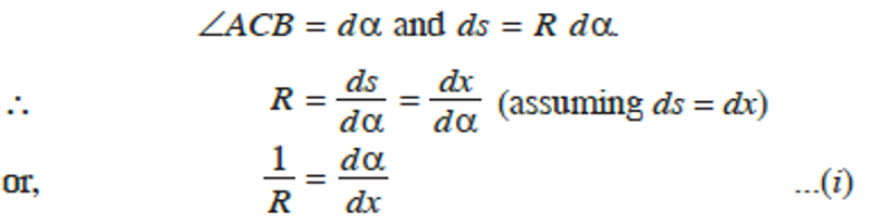
If the coordinates of point A are x and y, then:
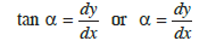
Differentiating the above equation with respect to x, we obtain
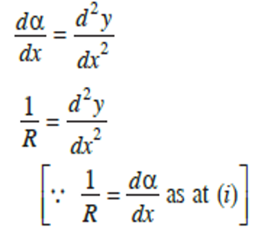
From bending theory of a beam, the expression relating the radius of curvature, moment of inertia, elastic modulus and moment is given by:
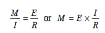
Now, if we substitute 1R=d2ydx2 into the above equation, we will have
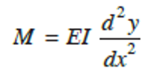
Units in the above equation include:
E = elastic modulus in N/m2
I = moment of inertia in m4
M = moment in Nm
y and x are taken in m.
This equation is the fundamental expression from which the slope and deflection in a beam can be calculated. Slope and deflection expressions can be obtained by carrying out double integration and applying boundary conditions of the beam to solve the expressions.
Sign Conventions
To find out the slope and deflection of a centre line of a beam at any point proper, there is need to use sign conventions. The following sign conventions will be used:
- x is positive when measured towards the right.
- y is negative when measured downwards.
- M (bending moment) is negative when hogging.
- Slope is negative when the rotation is clockwise.
Double integration Method
As we’ve seen, the fundamental equation for obtaining slope and deflection in beam is

Note that first integration of the above equation gives the value of slope (dydx). The second integration of the expression gives the value of the deflection (y).
Simply supported beam of span l carrying a point load at mid span.
Let‘s consider a simply supported beam AB of span l carrying a point load W at mid-span C, shown in Fig 19. Since the load is symmetrically applied, the maximum deflection (ymax) will occur at mid span.
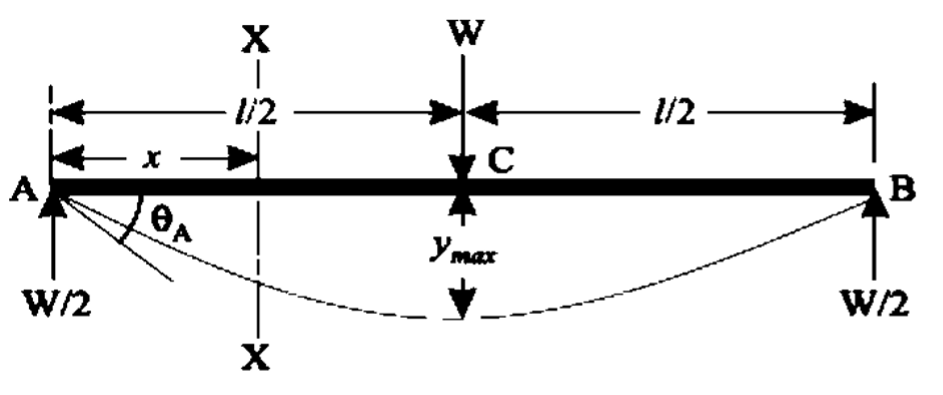
The support reactions at A and B equals = W2
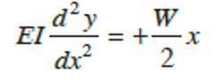
Consider the left half AC of the span. The bending moment at any section XX in AC distance. x from A is given by,
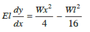
First integration gives,
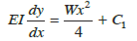
Where C1 is the constant of integration.
Applying boundary conditions: at
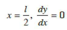
Thus we have,
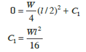
Substituting the value of C1 gives
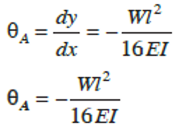
Slope (dydx) at the support A, i.e when x = 0
Therefore,
Integrating the slope equation once more, gives

and again using the boundary conditions:
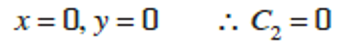
Hence, we have
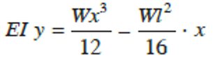
which is the deflection equation. Substitute x = l2 to obtain the mid-span deflection
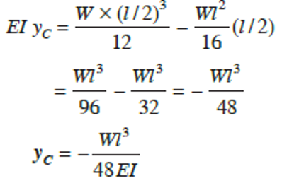
Hence, deflection at C, equals

Example of a 4m span beam
A simply supported beam with a 4 m span carries a uniformly distributed load of 20 kN/m on the whole span. Calculate the maximum slope and deflection of the beam. Take E = 2 105 N/mm2 and I = 5000 104 mm4.
Length of beam = 4 m
UDL = 20 kN/m = 20000 N/m
E = 2 105 N/mm2 = 2 1011 N/m2
I = 5000 104 mm4 = 0.00005 m2
Slope is given by wl324EI = 20000 4324 2 1011 0.00005 = 5.3310-3 rad
Maximum deflection (occurring at midspan) is given by ymax= 5wl4384EI = 520000443842 1011 0.00005 = 0.00667 m
Keep an eye out for future articles on more engineering calculations, tips and explanations.
Interested in our courses?
Interested in civil or mechanical engineering? Find out more about all the civil engineering courses we have available by clicking here, and the mechanical engineering courses by clicking here.
Diploma in Mechanical Technology
Diploma in Mechanical Engineering
Diploma in Sustainable Construction
Diploma in Structural Engineering
Diploma in Building and Construction Engineering
Higher International Certificate in Civil Engineering
Higher International Diploma in Civil Engineering
Higher International Diploma in Mechanical Engineering
Higher International Certificate in Mechanical Engineering
Alternatively, you can view all our online engineering courses here.
Recent Posts
Essential Formulas for Calculating Drilling Parameters
Essential Formulas for Calculating Drilling Parameters When it comes to precision and efficiency in manufacturing, few processes are as foundational—or as critical—as drilling. Whether you’re a seasoned engineer or a student entering the world of mechanical or industrial engineering, understanding how to correctly calculate drilling parameters can significantly impact the quality of your work, the […]
From Raw Material to Refined Component: The Role of Drilling and Turning
From Raw Material to Refined Component: The Role of Drilling and Turning Secondary processes are used in manufacturing to further modify the output of primary manufacturing processes in order to improve the material properties, surface quality, surface integrity, appearance and dimensional tolerance. In this blog, we will focus on drilling and turning as secondary manufacturing […]
Behind the Cutter: How Milling Shapes the Future of Manufacturing
Behind the Cutter: How Milling Shapes the Future of Manufacturing Secondary processes are used in manufacturing to further modify the output of primary manufacturing processes in order to improve the material properties, surface quality, surface integrity, appearance and dimensional tolerance. In this blog, we will focus on milling as a secondary manufacturing process. Machining refers […]