How to calculate stress for direct loading of components.
If a rubber strip is pulled it stretches, and the more you pull it the more it stretches. There’s a relationship between the extension and the force applied, known as Hooke’s Law, and it can be expressed as a force extension graph:
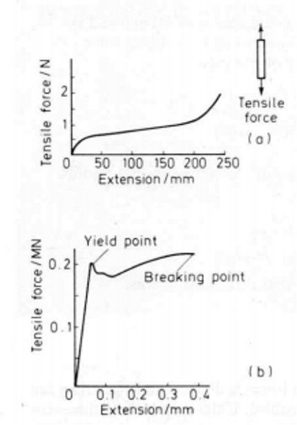
The top graph above shows the graph we’d see for a strip of rubber, and the bottom graph shows a piece of steel. You’ll notice that the forces needed to stretch steel are considerably greater than for rubber. We can also see, from looking at the extension axis, that the amount by which rubber changes length is greater than that of steel.
You can also see that the overall shapes of the graphs are very different. The rubber, after a small force, needed very little increase in force to produce greater extensions. After an extension of about 200 millimeters, the rubber becomes much more difficult to stretch. The steel needs quite large forces to produce any extension. However, when the force reaches 0.2 MN (0.2 x 10⁶), the steel increases considerably in length without any more force being applied. The steel is said to have yielded.
Force Applied Calculation
The force is applied to the rubber and the steel strips, resulting in an increase in the lengths of the strips. The forces are said to be tensile forces and the strips are in tension. If the cross-sectional area of the strip is doubled, then twice the forces are needed to give the same extension. If the cross-sectional area is 3 times larger, then the force must be three times larger to get the same extension. For the same extension, the force per unit area should be constant. This quantity is called stress:
stress=force area
σ=FA
Where F is the force (N) and A is the area (m2). The units of stress are N/m2 or Pa (1 Pascal = 1N/ m2).
Direct or Normal Stress.
Look at the image below, with a bar of length L. Constant cross-sectional area A is subjected to an axial tensile force F.
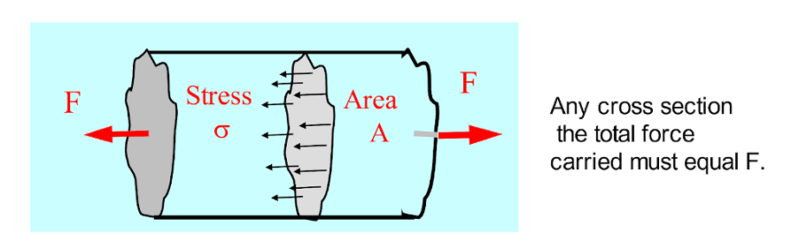
When the force is uniformly distributed over the section, then:

The stress is said to be direct stress when the area being stressed is at right angles to the line of action of the force, as is the case as shown with the rubber graph above.
Let’s look at an example. A specimen with a cross-sectional area of 50mm2 was subjected to a tensile force of 0.1 MN. We’re going to calculate the stress induced in this specimen.
Firstly, we convert the values to SI units:
1mm2 = 0.001 x 0.001m2 = 1 x 10 – 6m2
Therefore, 50mm2 = 50 x 10 = 6m2
σ=FA=0.1x10650x10-6=2×109=2GPa
Keep an eye out for more of our articles where we dive deeper into some of these concepts.
Interested in our courses?
Interested in civil or mechanical engineering? Find out more about all the civil engineering courses we have available by clicking here, and the mechanical engineering courses by clicking here.
Diploma in Mechanical Engineering
Diploma in Mechanical Technology
Diploma in Sustainable Construction
Diploma in Structural Engineering
Diploma in Building and Construction Engineering
Higher International Certificate in Civil Engineering
Higher International Diploma in Civil Engineering
Higher International Diploma in Mechanical Engineering
Higher International Certificate in Mechanical Engineering
Alternatively, you can view all our online engineering courses here.
Recent Posts
Civil Engineering Courses and Diplomas: Topics, Skills and Career Routes
Civil Engineering Courses and Diplomas: Topics, Skills and Career Routes Introduction Civil engineering is the backbone of modern society. From roads and bridges to skyscrapers and water systems, civil engineers design, build, and maintain the infrastructure that keeps the world running. If you’re considering a civil engineering course or diploma, understanding what it covers is […]
What Is a Diploma in Engineering? Courses, Levels and Career Routes Explained
What Is a Diploma in Engineering? Courses, Levels and Career Routes Explained Introduction Engineering shapes the world around us, from the buildings we live in to the technology we use every day. But for many aspiring engineers, the biggest question is not whether to pursue engineering, but how to start. Traditional university degrees are not […]
Engineering Courses: How to Choose the Right Route for Your Career
Engineering Courses: How to Choose the Right Route for Your Career Introduction Choosing an engineering course can feel like standing at the beginning of several different roads, each leading towards a different kind of future. One route may lead into mechanical systems and manufacturing. Another may lead towards aircraft, infrastructure, electronics, computing, renewable energy or […]