How do we Measure Airspeed and Altitude of Aircraft?
Measuring the airspeed and altitude of an aircraft it is not as simple as you might first think, and requires the consideration of a number of different factors. In this article we will introduce the different types of aircraft airspeed and altitude, why they are important and how they are measured.
Airspeed Measurement
There are 4 types of airspeed often referred to:.
- Indicated Airspeed(IAS): the value that is read directly off the airspeed indicator, calculated from the pitot static system.
- True Airspeed (TAS): the speed of the aircraft relative to the air it’s flying through. At higher altitudes, true airspeed is higher than your indicated airspeed.
- Groundspeed (GS): the movement of the aircraft relative to the ground. It is the true airspeed with a correction for wind.
- Calibrated Airspeed (CAS): the indicated airspeed corrected for instrument and positional errors.
A brief overview of the principles behind which the devices work will be given below.
Indicated Airspeed.
The air speed indicator is located in the cockpit of an aircraft. It is a device for measuring forward speed of an aircraft. Airspeed is measured in knot or kilometres per hour.
On older aircraft, airspeed is usually indicated to the pilot on a graduated scale over which a pointer moves ( the first diagram). In modern aircraft, airspeed is usually indicated on a speed tape which forms part of the electronic flight instrument system display ( the second diagram).

Figure 1 – Air speed indicators
The air speed indicators are fed information from a pitot-static system (shown below), which involves calculating the airspeed from the differences in stagnation and static pressures recorded via a pitot tube.
Pitot tubes are used to measure air flow in pipes, ducts, and stacks, and liquid flow in pipes.
While accuracy and rangeability are relatively low, pitot tubes are simple, reliable, inexpensive, and suited for a variety of environmental conditions.
The total impact pressure is the sum of the static and dynamic pressures and is detected as the flowing stream impacts on the pitot opening. To measure impact pressure most pitot tubes use a small, L-shaped tube, with the opening directly facing the oncoming flow stream.

Figure2 – Pitot tube
Figure 2
Note: the static ports are at right angles to the flow (which measure the static pressure) and the velocity inlet facing the flow (which measures the dynamic pressure) and can be found using Bernoulli’s principle.

Pitot Tube
The photograph below shows a pitot tube on an aircraft.

Pitot Tube for Measuring Airspeed
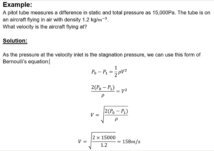
Bernoulli’s principle states that the difference between the stagnation and static pressure is the dynamic pressure, from which velocity can be found:

Where:
Po is the stagnation pressure measured in Pascals (Pa)
P1 is the static pressure measured in Pascals (Pa)
p is the density measured in kg/m^3
and V is the velocity measured in m/s

Example Airspeed Calculation using Pitot Tube
The location of the Pitot tubes is vital in order to reduce error caused by airflow over the aircraft to a minimum.
Commercial aircraft have at least two completely independent pitot systems to provide redundancy in the case of system failure.
To reduce contamination by moisture and prevent blockage by ice they are electrically heated.
Blockages in pitot tubes can be caused by:
- In-Flight Icing
- Insects
- Volcanic Ash
- Heavy rain
- Crude Oil Smoke
- Failure to remove maintenance seals or protective covers from external vents prior to flight
- Failure to select pitot static heat on
- Damage to the nose cone of an aircraft causing erroneous pitot and static information.
If the pitot probe is blocked but the pitot drains and static ports are free, then in straight and level flight the displayed IAS will tend to reduce, eventually indicating zero.
If the pitot probe and pitot drain are blocked but the static port is free, then the IAS will increase during a steady climb and decrease during a steady descent.
True Airspeed
The true airspeed is dependant on the density and temperature of the air.
At slow speeds the air density can be treated as equal to international standard atmospheric values, but these values become inaccurate when conditions change.
If the air density and temperature decrease, the IAS will be lower than the true air speed.
The true air speed can’t be measured directly and a series of calculations must be carried out by onboard computers using data on static air temperature and pressure in real time.
As the speed and altitude increase to around 100 knots, the error in the air density increases significantly.
For speeds above 300 knots we apply a Mach number which incorporates these errors.
Groundspeed
The groundspeed of an aircraft is its speed in relation to the surface of the Earth
The groundspeed involves a vector calculation of the true airspeed and the wind direction and strength

Measuring Groundspeed
Groundspeed is essential in air traffic control:
- Estimate calculation: the groundspeed is used to calculate the arrival time of aircrafts, and hence the transfer of control points.
- Conflict management: Using groundspeed allows for flight paths to be changed when necessary, as groundspeed depends in wind patterns.
Calibrated air speed
The calibrated air speed is the value obtained when the instrument and position errors ( caused by pressure) are taken into account.
Uses of Calibrated airspeed:
- Navigation: due to GPS and inertial navigation system, this is no longer essential as the pilots have access to true airspeed and groundspeed directly
- Aircraft control: This application is essential as it takes into account aircraft weight, rotation whilst climbing and allows for landing speed to be determined
Altitude Measurement
Altitude is defined as the vertical distance between the object and the points of reference. As the aircraft is moving, this is not a simple measurement to take.
Just like airspeed, there are different methods of determining altitude.
- Indicated Altitude – This the measurement indicated on the altimeter. This is calculated using readings from pressure sensors, radar systems and lasers.
- True Altitude – This uses the average sea level as the point of reference.
- Pressure Altitude – Pressure altitude is a measurement of the aircraft’s altitude above a standard datum plane and is indicated by setting the altimeter to 29.92.
- Density Altitude – Density altitude is pressure altitude corrected for nonstandard temperature conditions, which include pressure, humidity, and temperature that’s outside the normal readings.
- Absolute Altitude – This refers to the actual distance the aircraft is flying above the current ground level at an instant. This distance will usually be found using a radar altimeter.
Methods of Measuring Altitude:
As altitude can be determined by values other than simple distance from the ground, there are a range of different devices that can be used, the most common ones are discussed below
Barometric Altimeters – a barometric altimeter uses changes in air pressure to calculate the altitude, since the air pressure decreases as altitude increases.
However, air pressure can also fluctuate due to changes in the weather so these variables must be accounted for to get an accurate reading

Radio Altimeters – Electromagnetic waves that fall into the radio section of the spectrum are generated and these will reflect off the surface of the earth or sea, the time taken to receive the reflection is measured.
Using distance = speed x time the distance can be calculated as they travel at the speed of light and the time has been measured.. The value must then be halved as we have measured the time to the ground and back

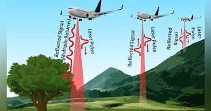
Laser Altimeters – Electromagnetic waves within the visible range of the spectrum instead of radio waves. The time taken for the emitted signal to travel from the transmitter to the surface and back again is measured.
The reflected beam of light is received and collected using a series of mirrors and lenses which focus the beam onto a photocell detector which is sensitive to infrared light.

Aerospace Engineering Courses
To learn more about aerospace engineering including the principles of flight, aerodynamics, aircraft design please see the wide range of online aerospace courses and qualifications available from iLearn Engineering®.
Why not check out the online engineering short courses specifically in aerospace engineering:
Diploma in Aerospace Structures
Diploma in Principles of Flight
Diploma in Aerodynamics, Propulsion and Space
Alternatively, you can view all our online engineering courses here.
Recent Posts
Kirchhoff’s current and voltage laws
Kirchhoff’s current and voltage laws In our last article, we looked at the principles and operation of a d.c motor. In this article, we’re going to investigate Kirchoff’s current and voltage laws, as well as how to apply them to engineering problems. Kirchoff’s law of current Kirchoff’s law of current states that the algebraic sum […]
What are the principles of operation of a DC electric motor?
What are the principles of operation of a DC electric motor? In our last article, we looked at the electrical parameters in series and parallel electrical circuits. In this article, we’re going to dive into the principles of operation of a DC electric motor. The motor effect When a current-carrying conductor is placed on a […]
What are the electrical parameters in series and parallel electrical networks?
What are the electrical parameters in series and parallel electrical networks? In our last article, we looked at the principles of operation of electrical cells. In this article we’re going to move on to the electrical parameters in both series and parallel electrical networks. When we have circuits with more than one resistor, we need […]

